Инструкция для Indesit PA-64-S-(IX)
 1
1 2
2 3
3 4
4 5
5 6
6 7
7 8
8 9
9 10
10 11
11 12
12 13
13 14
14 15
15 16
16 17
17 18
18 19
19 20
20 21
21 22
22 23
23 24
24 25
25 26
26 27
27 28
28
GB
9
longevity of your appliance while maintaining efficient
energy consumption.
Connection with a rigid pipe (copper or steel)
! Connection to the gas system must be carried out in such a
way as not to place any strain of any kind on the appliance.
There is an adjustable L-shaped pipe fitting on the appliance
supply ramp and this is fitted with a seal in order to prevent
leaks. The seal must always be replaced after rotating the
pipe fitting (seal provided with appliance). The gas supply
pipe fitting is a threaded 1/2 gas cylindrical male attachment.
Connecting a flexible jointless stainless steel pipe to
a threaded attachment
The gas supply pipe fitting is a threaded 1/2 gas cylindrical
male attachment.
These pipes must be installed so that they are never longer
than 2000 mm when fully extended. Once connection has
been carried out, make sure that the flexible metal pipe
does not touch any moving parts and is not compressed.
! Only use pipes and seals that comply with current national
regulations.
Checking the tightness of the connection
! When the installation process is complete, check the pipe
fittings for leaks using a soapy solution. Never use a flame.
Adapting to different types of gas
To adapt the hob to a different type of gas other than default
type (indicated on the rating plate at the base of the hob or
on the packaging), the burner nozzles should be replaced
as follows:
1. Remove the hob grids and slide the burners off their
seats.
2. Unscrew the nozzles using a 7 mm socket spanner, and
replace them with nozzles for the new type of gas (see
table 1 “Burner and nozzle characteristics”).
3. Reassemble the parts following the above procedure in
the reverse order.
4. Once this procedure is finished, replace the old rating
sticker with one indicating the new type of gas used.
Sticker are available from any of our Service Centres.
• Adjusting the burners’ primary air
Does not require adjusting.
• Setting the burners to minimum
1. Turn the tap to the low flame position;
2. Remove the knob and adjust
the adjustment screw, which is
positioned in or next to the tap pin,
until the flame is small but steady.
3. Having adjusted the flame to the required low setting,
while the burner is alight, quickly change the position
of the knob from minimum to maximum and vice versa
several times, checking that the flame does not go out.
4. Some appliances have a safety device (thermocouple)
fitted. If the device fails to work when the burners are set
to the low flame setting, increase this low flame setting
using the adjusting screw.
5. Once the adjustment has been made, replace the
seals on the by-passes using sealing wax or a similar
substance.
! If the appliance is connected to liquid gas, the regulation
screw must be fastened as tightly as possible.
! Once this procedure is finished, replace the old rating
sticker with one indicating the new type of gas used. Stickers
are available from any of our Service Centres.
! Should the gas pressure used be different (or vary slightly)
from the recommended pressure, a suitable pressure
regulator must be fitted to the inlet pipe (in order to comply
with current national regulations).
Electrical
connections
DATA PLATE
see data plate
This appliance conforms to the following
European Economic Community directives:
- 2006/95/EEC dated 12/12/06 (Low
Voltage) and subsequent amendments
- 2004/108/EEC dated 15/12/04
(Electromagnetic Compatibility) and
subsequent amendments
- 93/68/EEC dated 22/07/93 and
subsequent amendments.
- 2009/142/EEC dated 30/11/09 (Gas) and
subsequent amendments.
- 2012/19/EC and subsequent
amendments.
Оглавление инструкции
- Страница 1 из 29
PA 64 S MPA 64 S Қазақша Пайдалану нұсқаулығы ПЛИТА Мазмұны Пайдалану нұсқаулығы,1 Ескертулер,3 Көмек,4 Құрылғы сипаттамасы,6 Орнату,21 Қосу және пайдалану,25 Сақтандырулар мен кеңестер,25 Жөндеу және күтім,26 Ақаулықтарды жою,26 English Operating Instructions HOB Contents Operating Instructions,1
- Страница 2 из 29
Warnings Предупреждения WARNING: The appliance and its accessible parts become hot during use. Care should be taken to avoid touching heating elements. Children less than 8 years of age shall be kept away unless continuously supervised. This appliance can be used by children aged from 8 years and
- Страница 3 из 29
Удалите жидкость из крышки перед открытием. Не закрывать стеклянную крышку (если имеется) с газовыми горелками или электрическая плита еще горячая. ВНИМАНИЕ: Использование
- Страница 4 из 29
Assistance Communicating: • appliance model (Mod.) • serial number (S/N) This information is found on the data plate located on the appliance and/or on the packaging. Сервисное обслуживание Перед тем как обратиться в Центр Технического Обслуживания: • Модель изделия (Мод.) • Номер тех. паспорта
- Страница 5 из 29
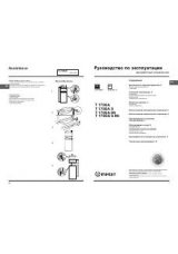
Description of the appliance Описание изделия Overall view Общии вид 1 2 5 8 9 1 2 5 8 9 Support Grid for Cookware Gas burners Control Knobs for gas burners Ignition for Gas burners* Safety devices* Опорные решетки для КАСТРЮЛЬ И СКОВОРОД ГАЗОВЫЕ КОНФОРКИ Регуляторы ГАЗОВЫХ КОНФОРОК Свеча зажигания
- Страница 6 из 29
Құрылғы сипаттамасы Жалпы шолу 1 2 3 4 5 Ыдыстарға арналған тіреуіш тор Газ оттықтары Газ оттықтары басқару тұтқалары Газ оттықтарының тұтату құралы Қауіпсіздік құрылғылары • Газ оттықтары өлшемі мен қуатына қарай әртүрлі болады. Тамақ пісіру үшін тиісті оттықты ыдыстың диаметріне қарай таңдаңыз. •
- Страница 7 из 29
Positioning ! Keep packaging material out of the reach of children. It can become a choking or suffocation hazard (see Precautions and tips). ! The appliance must be installed by a qualified professional according to the instructions provided. Incorrect installation may cause harm to people and
- Страница 8 из 29
30 20 Hook fastening diagram and frequency indicated on the data plate (this is located on the lower part of the appliance). The earth wire in the cable has a green and yellow cover. If the appliance is to be installed above a built-in electric oven, the electrical connection of the hob and the
- Страница 9 из 29
longevity of your appliance while maintaining efficient energy consumption. Connection with a rigid pipe (copper or steel) ! Connection to the gas system must be carried out in such a way as not to place any strain of any kind on the appliance. There is an adjustable L-shaped pipe fitting on the
- Страница 10 из 29
GB Burner and nozzle specifications Table 1 Liquid Gas Diameter Burner (mm) Thermal Power kW (p.c.s.*) By-pass 1/100 Nozzle 1/100 Naturale Gas Flow* g/h Nozzle 1/100 Nom. Red. (mm) (mm) *** ** (mm) Flow* l/h Fast (R) 100 3.00 0.70 41 86 218 214 116 286 Semi Fast (S) 75 1.90 0.40 30 70 138 136 106
- Страница 11 из 29
Start-up and use Precautions and tips ! The position of the corresponding gas burner is shown on every knob. ! This appliance has been designed and manufactured in compliance with international safety standards. The following warnings are provided for safety reasons and must be read carefully. Gas
- Страница 12 из 29
GB • Do not let children play with the appliance. • IMPORTANT SAFETY INFORMATION FOR UK MARKET: Please note that this product is not fitted with a flame supervision device. It is NOT suitable for fitting or use in high rise flats or multiple dwellings. If you are in any doubt please contact a CORGI
- Страница 13 из 29
Установка ! Важно сохранить данное руководство для его последующих консультации. В случае продажи, передачи изделия или при переезде на новое место жительства необходимо проверить, чтобы руководство оставалось вместе с изделием, для того чтобы его новыи владелец мог ознакомиться с правилами
- Страница 14 из 29
RS Если варочная панель устанавливается сверху встроенного духового шк афа, не оснащенного принудительнои охладительнои вентиляциеи, для надлежащеи вентиляции внутри кухонного элемента необходимо проделать вентиляционные отверстия для циркуляции воздуха (см чертежи). 555 mm m mm m 475 55 Схема
- Страница 15 из 29
штепсельнои вилкои изделия. В противном случае замените розетку или вилку; не используите удлинители или троиники. ! Изделие должно быть установлено таким образом, чтобы электрическии провод и сетевая розетка были легко доступны. ! Электрическии провод изделия не должен быть согнут или сжат. ! Ре г
- Страница 16 из 29
RS регуляционныи винт должен быть завинчен до упора. ! По завершении операции замените старую этикетку тарирования на новую, соответствующую новому типу используемого газа. Этикетку можно заказать в наших Центрах Технического Обслуживания. ! Если давление используемого газа отличается от
- Страница 17 из 29
RS Характеристики конфорок и форсунок Сжиженный газ Таблица 1 Горелка Тепловая мощность кВт (p.c.s.*) Диаметр Байпас Форсунка 1/100 1/100 Природный газ расход* гр/час Форсунка 1/100 расход* л/час (мм) Номинальная Cокращенная (мм) (мм) *** ** (мм) Быстрая (R) 100 3.00 0.70 41 86 218 214 116 286
- Страница 18 из 29
RS Включение и эксплуатация ! Н а к а ж д о и р у к о я т к е п о к а з а н о п ол о ж е н и е соответствующеи конфорки на варочнои панели. Газовые конфорки При помощи соответствующего регулятор можно выбрать один из следующих режимов конфорки: ● Выключено Минимальныи Для зажигания однои из
- Страница 19 из 29
сетевои розетки. • В случае неисправности категорически запрещается открывать внутренние механизмы изделия с целью их самостоятельного ремонта. Обращаитесь в Центр Сервисного обслуживания (см. Техобслуживание). • Следите, чтобы ручки кастрюль на варочнои панели были всегда повернуты таким образом,
- Страница 20 из 29
RS Конфорка не зажигается, или пламя горит неравномерно. Форсунки газовои конфорки засорились. • Все съемные части конфорки дожны быть установлены правильно. • Сквозняки рядом с газовои варочнои панелью. В моделях варочнои панели, оснащенных защитным устроиством, конфорка загорается и сразу гаснет.
- Страница 21 из 29
Орнату газдың шығуы жағдайында, ол бөлмеден шығып кетуі үшін вентиляциялық тесіктермен жабдықталуы тиіс. Сол себепті, сығылған газ баллондары, жартылай немесе толық болса да, жер деңгейінен төмен бөлмелерде не сақтау аумақтарында (төле және т.б.) орнатылмауы немесе сақталмауы тиіс. Тек
- Страница 22 из 29
Алды Құрылғы тікелей электр желісіне құрылғы мен электр желісі арасында орнатылған 3 мм ашық кішкене байланыс бар бірнеше каналды айырып-қосқыш арқылы қосылуы қажет. Айырып-қосқыш көрсетілген жүктемеге лайықты және ағымдағы ток реттеуіне сәйкес болуы қажет (жерге қосылған сым айырып-қосқыштан
- Страница 23 из 29
Қатты түтік арқылы жалғау (мыс немесе болат) ! Газ жеткізу жүйесіне жалғауды кез келген құрылғыға еш жүк түспейтін түрде іске асыру керек. Құрылғының жабдықтары жинағында реттелмелі L-пішініндегі түтік фитингі бар және оның газдың шығып кетуінің алдын алатын тығыны бар. Түтік фитингін әр бұраған
- Страница 24 из 29
KZ IT Отты пен форсункаларды сипаттары Сұйық газ 1-кесте Оттық Диаметр (мм) Жылу қуаты, кВт (p.c.s.*) Номиналды Азайтылған Табиғи газ Форсунка 1/100 Ағым* г/сағ Айналып өт 1/100 Форсунка 1/100 (мм) (мм) *** ** (мм) Ағым* л/сағ Жылдам (R) 100 3.00 0.70 41 86 218 214 116 286 Жартылай жылдам (S) 75
- Страница 25 из 29
Қосу және пайдалану қауіпсіздік ережелерін ескерту мақсатында берілген және оны мұқият оқып шығу қажет. ! Тиісті газ оттығының немесе электр конфорканың* орны әрбір тұтқада көрсетілген. Жалпы қауіпсіздік Газ оттықтары Әрбір оттықты тиісті басқару тұтқасының көмегімен төмендегі параметрлердің біріне
- Страница 26 из 29
KZ IT бақылайтын құралмен жабдықталмағанын ескеріңіз. Ол көп қабатты үйлерде немесе көп пәтерлі үйлерде қолдануға АРНАЛМАҒАН. Күмәндансаңыз, CORGI ұйымында тіркелген газ маманынан кеңес алыңыз. • Құрылғы сыртқы таймермен немесе бөлек қашықтан басқару жүйесімен басқарылуға арналмаған. Қоқысқа тастау
- Страница 27 из 29
IT KZ 27
- Страница 28 из 29
195107750.00 02/2013 - XEROX FABRIANO KZ IT 28
- Страница 29 из 29